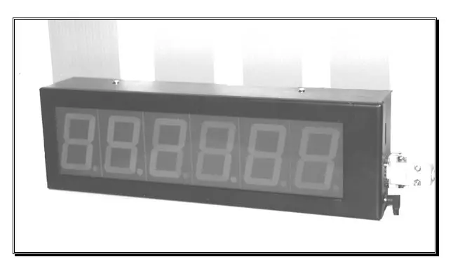
21.10 Et9010 Clock Display
Clock Display
Printing History
ET9010 - User’s Guide 7/16/2001 10:07:00 AM02
All information contained in this guide can be subjected to changes without notice or obligation.
Copyright
© 1989 – 2000 ETERE
Contents of this publication may not be reproduced in any form without the written permission of ETERE. Reproduction or reverse engineering of copyrighted software is prohibited.
Disclaimer
ETERE makes no representations or warranties with respect to the contents hereof and specifically disclaims any implied warranties of merchant ability or fitness for any particular purpose. Further, ETERE reserves the right to revise this publication and to make changes from time to time in the contents hereof without obligation of ETERE to notify any person of such revision or changes.
Company Address
ETERE s.r.l.
Contrada Cisterna.
62029 Tolentino (MC) — Italy
PO Box n 129
Tel: +39 0733 9564
Fax: +39 0733 956335
http:\\www.etere.com
Email: info@etere.com
Sommario
1. TRANSMISSION PROTOCOL....... 1
2. POWER ............................................... 1
3. BRILLIANCE ADJUSTMENT........... 1
APPENDIX A SIDE PANEL ................ 2
APPENDIX A SIDE PANEL ................ 2
1. TRANSMISSION PROTOCOL
Data transmission protocol is:
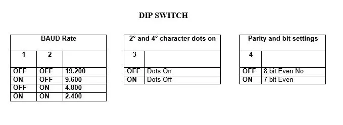
Speed: Variable 2400, 4800, 9600, 19200 (DIP Switch)
Bit n.: 7 o 8 “
Parity: Even o No “
Stop Bit: 1
The control line is:
STX (02Hex), Byte1, Byte2, Byte3, Byte4, Byte5, Byte8, ETX (03Hex)
Byte 1 = ASCII value for the 1° display (left side)
Byte 6 = ASCII value for the 6° display (left side) (1° right side)
Communication begins with a Start transmission STX (O2 Hex) (the preceding values will be ignored), and finishes with an End Transmission ETX (O3 Hex). The data visualisation only happens thanks to the End Transmission byte.
If there are more than 6 bytes between STX and ETX, only the first 6 will be considered.
Visible characters are: 0 1 2 3 4 5 6 7 8 9 -.
2. POWER
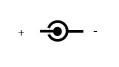
A connector for a 18 Volt 300mA D.C. power supply (included).
POWER
3. BRILLIANCE ADJUSTMENT
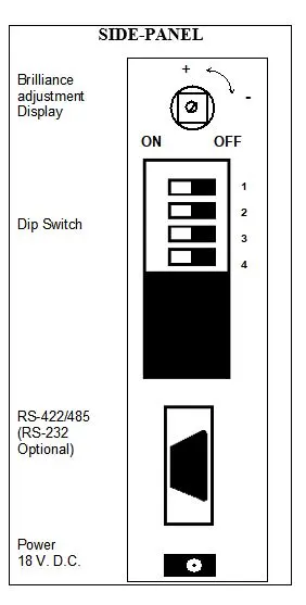
The trimmer (placed at the DIP Switch side) allows the Display brilliance adjustment. Turning in a clockwise direction the brilliance decreases, while in the opposite direction the brilliance increases.
APPENDIX A: SIDE-PANEL
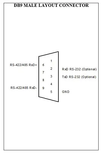
DB9 MALE LAYOUT CONNECTOR
SIDE-PANEL
DIP SWITCH
APPENDIX B: WIRING
Single and multiple 232 connection
PC DISPLAY
DB9F DB9F
Tx 3 9 Rx D+
GND 5 6 Rx D-
Rx D+
Single 232 connection
PC DISPLAY
DB25F DB9F
Tx 2 9 Rx D+
GND 7 6 Rx D-
Single 422 (ET0801) connection
PC DISPLAY
DB25F DB9F
Tx D+ 2 9 Rx D+
Tx D- 14 6 Rx D-
Multiple 422 (ET0811) connection
PC DISPLAY
DB9M DB9F
Tx D+ 3 9 Rx D+
Tx D- 8 6 Rx D-